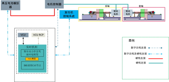
This platform is a power‑level hardware‑in‑the‑loop (HiL) system dedicated to the strategy development and testing of a vehicle control unit (VCU) for new energy vehicles. It serves as a key component of a complete three‑electric‑system (battery, motor, electronic control) test environment. Unlike conventional signal‑level HiL systems, the battery management system (BMS) is implemented as a software‑based virtual ECU (soft ECU) within the simulation environment, while the motor control unit (MCU) and the drive motor are retained as physical devices and connected to an actual dynamometer test bench. Only the VCU requires a dedicated HiL rack, which is then co‑debugged with the dynamometer bench hosting the MCU and the drive motor.
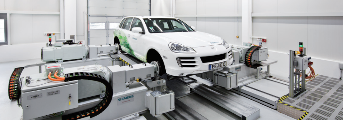
This architecture creates a “virtual‑physical hybrid, power‑closed‑loop” test environment: the VCU HiL rack simulates the rest of the vehicle environment (e.g., driver intent, vehicle dynamics, battery model), while the real MCU and motor run on the dynamometer bench according to VCU commands, with the dynamometer loading road resistance. Both sides work together to validate VCU control strategies under near‑real power flow conditions, including torque coordination, mode switching, regenerative braking, and fault diagnostics.
To achieve low‑latency, high‑determinism data exchange, two communication methods are implemented:
-
CAN bus communication – used for information exchange between the VCU and the MCU. The VCU sends target torque/speed commands to the MCU via CAN and receives feedback on actual motor status (speed, temperature, fault codes, etc.). This channel carries all periodic control messages and diagnostic information, following the vehicle network protocol for new energy vehicles.
-
Hardwired signal interaction – used for real‑time control signals and parameter transmission between the HiL rack and the dynamometer bench. Because power‑level testing demands extremely high real‑time performance, hardwired connections (digital I/O, analog signals, pulse trains) directly transmit driver pedal signals, emergency stop signals, actual motor speed pulses, torque sensor outputs, etc., avoiding the unpredictable latency introduced by bus protocol stacks and ensuring the stability and safety of closed‑loop control.
The VCU HiL rack is built on an NI real‑time simulation platform (e.g., PXIe), running a Simulink‑based vehicle longitudinal dynamics model, a battery equivalent circuit model, and the soft BMS model. The rack is also equipped with signal conditioning and fault injection modules to simulate sensor faults, power supply fluctuations, bus frame loss, and other abnormal scenarios, subjecting the VCU to rigorous boundary testing. By using the real motor load on the dynamometer bench, this platform effectively validates the VCU’s response time, electromagnetic compatibility, and thermal management strategies under near‑production power levels, significantly reducing the risks and costs of real‑vehicle road testing.
This power‑level HiL system is particularly suitable for VCU extreme‑condition tests (e.g., high‑torque launch, hard acceleration, regenerative braking overload), controller‑in‑the‑loop regression testing, and pre‑calibration for vehicle integration, providing reliable assurance for three‑electric‑system integration.